The IEEE 1394-1995 standard for the High Performance Serial Bus, here abbreviated to 1394, defines a serial data transfer protocol and interconnection system that "provides the same services as modern IEEE-standard parallel busses, but at a much lower cost." 1394 incorporates quite advanced technology, but it's the "much lower cost" feature that assures 1394's adoption for the digital video and audio consumer markets of 1997 and beyond. The capabilities of the 1394 bus are sufficient to support a variety of high-end digital audio/video applications, such as consumer audio/video device control and signal routing, home networking, nonlinear DV editing, and 32-channel (or more) digital audio mixing. Sony's DCR-VX700 and DCR-VX1000 digital video (DV, formerly called DVC) camcorders, introduced in September 1995, were the first commercial products to implement 1394. Subsequently Sony introduced in late 1996 its DCR-PC7 micro-DV camcorder and Matsushita announced in early 1997 Japanese availability of the Panasonic NV-DE3 DV camcorder with a 1394 connector. IEEE - 1394 Features - Real-time data transfer for multimedia applications
- 100 and 200Mbits/s data rates today; 400- 800 Mbits/s and mul ti-Gbits/s upgrade path
- Live connection/disconnection without data loss or interruption
- Automatic configuration supporting "plug and play"
- Freeform network topology allowing mixing branches and daisy-chains
- No separate line terminators required
- Guaranteed bandwidth assignments for real-time applications
- Common connectors for different devices and applications
- Compliant with IEEE-1394 High Performance Serial Bus standard
This objective of this paper is to describe the architecture of 1394 bus systems, typical consumer video and audio applications for 1394, initial implementations of 1394 connectivity on PCI adapter cards, and the commercial adapter card designs that are scheduled for availability by mid-1997 for digital video editing applications. A brief comparison of the IEEE 1394 High Performance Serial Bus with the proposed Universal Serial Bus (USB) appears at the end of this paper. The orientation of this paper is toward consumer- and professional-grade DV products, because DV is the first application (and is likely to be the highest-volume application through 1998) for the High Performance Serial Bus. You can obtain the final version of the IEEE 1394-1995 standard from the Institute of Electrical and Electronic Engineers, Inc., Customer Service, 445 Hoes Lane, P.O. Box 1331, Piscataway, NJ 08855-1331, voice (800)678-IEEE or (908)981-0060, fax (908)981-9667, e-mail customer.service@ieee.org The USB 1.0 specification is available from The Open Host Controller Interface (Open HCI) 1.0 specification, which applies to 1394 and USB hosts, is available from MICROSOFT. A wide variety of information on 1394-related products and activities is available from Adaptec Corp.'s site, and on Texas Instrument's IEEE-1394 Web pages, IEEE's Microcomputer Standards Committee commenced in 1986 a unification process for various serial bus implementations of the VME, Multibus II, and Future Bus standards. This effort resulted in the original development of what became the IEEE 1394-1995 standard in Fall 1995. 1394 is based on Apple Computer's original 1394 bus, which was intended as a low-cost replacement for or supplement to the SCSI bus that is a standard feature of Macintosh and PowerMac computers. Apple and SGS Thomson, which has an UK patent applicable to 1394, license their patents "on reasonable and non-discriminatory terms to anyone wishing to obtain a license." These licenses apply only to the point of first implementation, which means integrated circuits to implement 1394 connectivity, and thus are of no concern to most adapter card manufacturers or end users. Today's licensees primarily are 1394 chip manufacturers, such as Texas Instruments, Adaptec and Symbios Logic, plus consumer electronics firms like Sony that incorporate some of the 1394 technology within their own specialized processor chips. IEEE - 1394 Architecture The 1394 standard defines two bus categories: backplane and cable. The backplane bus is designed to supplement parallel bus structures by providing an alternate serial communication path between devices plugged into the backplane. The cable bus, which is the subject of this paper, is a "non-cyclic network with finite branches," consisting of bus bridges and nodes (cable devices). Non-cyclic meansthat you can't plug devices together so as to create loops. 16-bit addressing provide for up to 64K nodes in a system. Up to 16 cable hops are allowed between nodes, thus the term finite branches. A bus bridge serves to connect busses of similar or different types; a 1394-to-PCI interface within a PC constitutes a bus bridge, which ordinarily serves as the root device and provides bus master (controller) capability. A bus bridge also would be used to interconnect a 1394 cable and a 1394 backplane bus. Six-bit Node_IDs allow up to 63 nodes to be connected to a single bus bridge; 10 bit Bus_IDs accommodate up to 1,023 bridges in a system. This means, as an example, that the limit is 63 devices connected to a conventional 1394 adapter card in a PC. Each node usually has three connectors, although the standard provides for 1 to 27 connector per a device's physical layer or PHY. Up to 16 nodes can be daisy-chained through the connectors with standard cables up to 4.5 m in length for a total standard cable length of 72 m. (Using higher-quality "fatter" cables permits longer interconnections.) Additional devices can be connected in a leaf-node configuration, as shown in figure 1. All 1394 consumer electronic devices announced as of early 1997 have only a single connector; there are no currently are digital camcorders or VCRs that correspond to the devices with ID 3 or ID 5 shown in figure 1. Physical addresses are assigned on bridge power up (bus reset) and whenever a node is added or removed from the system, either by physical connection/disconnection or power up/down. No device ID switches are required and hot plugging of nodes is supported. Thus 1394 truly qualifies as a plug-and-play bus. 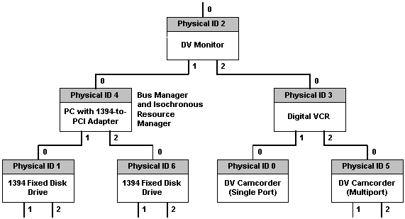
Fig. 1. Topology of a typical PC-based 1394 bus system for DV applications. Note: The topology shown in figure 1 assumes a common audio/video data format for all DV devices. For transmission on a single isochronous channel, devices must share the same data format. The Digital VCR Consortium (DVC) has prepared a standard for DV data formats and related control protocols for 1394, presently titled "General Specification for Consumer-Use Digital Interface." This standard is pending approval as International Electrotechnical Commission IEC1883, "Digital Interface for Consumer Electronics A/V." The 1394 cable standard defines three signaling rates: 98.304, 196.608, and 393.216 Mbps (megabits per second; MBps in this paper refers to megabytes per second.) These rates are rounded to 100, 200, and 400 Mbps, respectively, in this paper and are referred to in the 1394 standard as S100, S200 and S400. Consumer DV gear uses S100 speeds, but most 1394 PC adapter cards support the S200 rate. The signaling rate for the entire bus ordinarily is governed by the slowest active node; however, if a bus master (controller) implements a Topology_Map and a Speed_Map for specific node pairs, the bus can support multiple signaling speeds between individual pairs. The 1394 Trade Association's 1394.1 working group presently are refining and clarifying the setup requirements for handling interconnected devices with multiple signaling speeds. Physical, Link, and Transaction Layers The 1394 protocol is implemented by the three stacked layers shown in figure 2. The three layers perform the following functions: - The transaction layer implements the request-response protocol required to conform to the ISO/IEC 13213:1994 [ANSI/IEEE Std 1212, 1994 Edition] standard Control and Status Register (CSR) Architecture for Microcomputer Buses (read, write and lock). Conformance to ISO/IEC 13213:1994 minimizes the amount of circuitry required by 1394 ICs to interconnect with standard parallel buses.
- The link layer supplies an acknowledged datagram to the transaction layer. (A datagram is a one-way data transfer with request confirmation.) The link layer handles all packet transmission and reception responsibilities, plus the provision of cycle control for isochronous channels.
- The physical layer provides the initialization and arbitration services necessary to assure that only one node at a time is sending data and to translate the serial bus data stream and signal levels to those required by the link layer. Galvanic isolation may be implemented between the physical layer and the link layer; with isolation, the chip implementing the physical layer is powered by the bus conductors. Isolation should be provided where three-wire power cords are used to prevent ground loops through the green-wire ground; consumer devices, which use two-wire power cords or wall-wart power supplies, ordinarily don't require galvanic isolation.
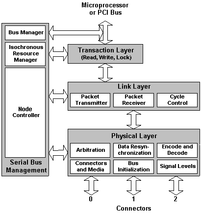
Fig. 2. The 1394 Protocol Stack and Serial Bus Management Controller. Cables and Connectors Standard bus interconnections are made with a 6-conductor cable containing two separately-shielded twisted pair transmission lines for signaling, two power conductors, and an overall shield (see figure 3). The two twisted pairs are crossed in each cable assembly to create a transmit-receive connection. The power conductors (8 to 40 v, 1.5 a max.) supply power to the physical layer in isolated devices. Transformer or capacitative coupling is used to provide galvanic isolation; transformer coupling provides 500 volts and lower-cost capacitative coupling offers 60 volts of ground potential difference isolation. Connectors are derived from the GameBoy design and use either a friction detent (standard) or the special side-locking tab restraints shown in figure 3.* (You squeeze the sides of the connectors for removal.) 1394 connectors are available from Molex and several other firms. 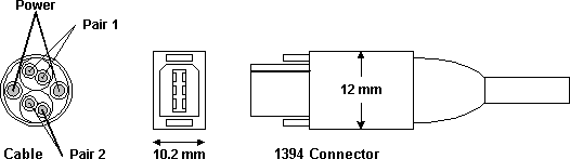
Fig. 3. 1394 cables and connectors. *The Sony DCR-VX700 and DCR-VX1000 camcorders and the DHR-1000 DVCR have only a single, non-standard 1394 connector to support DV input/output (output only in European versions). The four-conductor Sony connector, which is smaller than the standard 1394 connector and has only the signaling pairs (no power conductors), is defined in Part 1 of the draft of the proposed IEC standard and a forthcoming IEEE draft standard P1394.1. The Sony VMC-20V DV cable can interconnect two camcorders, but cannot connect to standard 1394 sockets without an adapter cable. These Sony camcorders act as terminating nodes and require a yet-undefined adapter for insertion as a leaf in a standard 1394 chain. DVCRs and other non-miniaturized consumer devices also use P1394.1 connectors. IEEE-1394Bus Management 1394 provides a flexible bus management system that provides connectivity between a wide range of devices, which need not include a PC or other bus controller. Bus management involves the following three services: - A cycle master that broadcasts cycle start packets (required for isochronous operation)
- An isochronous resource manager, if any nodes support isochronous communication (required for DV and DA applications)
- An optional bus master (a PC or an editing DVCR might act as a bus master)
On bus reset, the structure of the bus is determined, node IDs (physical addresses) are assigned to each node, and arbitration for cycle master, isochronous resource manager, and bus master nodes occurs. Figure 4 illustrates on a timeline the identification and arbitration processes that occur on bus reset. Note that during the 1-second delay isochronous resources that had been allocated before the reset are to be reallocated. Any resources that are not reclaimed will become available for future use. After that delay new resources may be allocated. 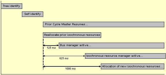
Fig. 4. Bus reset timeline. Isochronous Data Transport The isochronous data transport of the 1394 bus provides the guaranteed bandwidth and latency required for high-speed data transfer over multiple channels. The isochronous resource manager includes a BANDWIDTH_AVAILABLE register that specifies the remaining bandwidth available to all nodes with isochronous capability. On bus reset or when an isochronous node is added to the bus, the node requests a bandwidth allocation. As an example, a DV device would request approximately 30 Mbps of bandwidth, representing the 25+ Mbps DV data rate plus 3-4 Mbps for digital audio, time code, and packet overhead. Bandwidth is measured in bandwidth allocation units, 6,144 in a 125 ms cycle. (A unit is about 20 ns, the time required to send one data quadlet at 1,600 Mbps, called the S1600 data rate; the S1600 data rate is unlikely be supported in future implementations. A quadlet is a 32-bit word; all bus data is transmitted in quadlets.) 25 ms of the cycle is reserved for asynchronous traffic on the bus, so the default value of the BANDWIDTH_AVAILABLE register on bus reset is 4915 units. In a 100-Mbps system, a DV device would request about 1,800 units; in a 200-Mbps system, about 900 units would be sufficient. If adequate bandwidth is not available, the requesting device is expected to repeat its request periodically. The isochronous resource manager assigns a channel number (0 to 63) to nodes that request isochronous bandwidth based on values in the manager's CHANNELS_AVAILABLE register. All isochronous packets are identified by the assigned channel number. When a node no longer requires isochronous resources, it is expected to release its bandwidth and channel number. As an example, the bus manager sends signals to cause a camcorder to commence talking on its channel and a record deck to commence listening on its channel for video data from the bus manager application. Device control is managed by asynchronous communication. Video acquisition for non-linear digital editing is simpler than the camcorder-DVCR example, because it requires only a single isochronous channel, plus an asynchronous path for device control. Timecode is built into the DV data, but asynchronous timecode transmission over the bus is useful when in camcorder or DVCR shuttle mode. Consumer Electronics Applications for 1394 The majority of the informative illustrations in the 1394 standard show interconnections between consumer video devices, with and without attached PCs. Based on the draft standard, 1394 Trade Association documents, and conversations with members of the Association, following are the primary consumer electronics applications anticipated for the High Performance Serial Bus. The products are listed in the author's forecast order of their introduction to the retail market. - Digital camcorders and DVCRs (Sony DCR-VX700, DCR-VX1000, and DCR-PC7 camcorders, Sony DHR-1000 DVCR, Sony DSR-30 DVCAM DVTR, and new Panasonic DV camcorders)
- Digital videoconferencing systems using the Sony CCM-DS250 digital camera, which became generally available in early 1997
- Direct-to-home (DTH) satellite video and audio MPEG-2 data streams*
- Musical synthesizers with MIDI and digital audio capabilities, initially from Yamaha
- Printers for video and computer data
- Fixed and removable PC disk drives, internal and external
- PC-to-PC networking (the 1394 "home PC network") and PC peripheral component sharing
- Cable TV and MMDS ("wireless cable") set-top boxes
- Digital video disk (DVD) drives
*Thomson/RCA receivers for DirecTV and USSB DSS satellite programming presently have an unused high-speed parallel data port intended to transmit MPEG-encoded video and audio to a digital tape recorder for time-shift recording. A Thomson/Hitachi digital VCR using JVC's D-VHS 1/2-inch bitstream recording format was announced in 1994 for availability in early 1996, together with an upgraded version of the Thomson/RCA DBS receiver. Despite the press releases, this combination didn't arrive. At the 1997 Winter Consumer Electronics show, Hitachi exhibited a prototype of its DX815 D-VHS recorder, which uses a non-standard implementation of 1394 to connect the recorder to a Hitachi DSS set-top box. Thomson did not display a D-VHS deck, but is expected to announce a similar product later in 1997. The R-4.1 ATV Receiver Interface Subcommittee of the Consumer Electronics Manufacturers Association (CEMA, formerly the Consumer Electronics Group) of the Electronic Industries Association is supporting a proposal to the IEC TC84 committee for a transport layer over fully-compliant 1394 to handle MPEG-2 and other digital data streams associated with Digital (Standard- and High-Definition) TV. A principal advantage of the use of 1394 to interconnect DV and digital audio (DA) gear is that the 1394 bus is operable without a bus manager, and any "talker" device can arbitrate for assignment as the isochronous resource manager. Thus a DV camcorder, simple DVCR, printer, and DTV set can be connected without the need for a PC or other device to act as a bus manager. Assuming the camcorder is the "talker" and all other devices are "listeners," only a single, fixed isochronous channel is required. The camcorder starts talking in response to a local or remote control device, and the other DV devices listen or not, depending on their control status. One also could create a low-end equivalent of the $60,000+ Avid/Ikegami fixed-disk camcorder (CamCutter) with a battery-powered 1394 fixed or removable disk drive in a belt-pack, assuming the disk drive has enough built-in "smarts" to handle disk I/O chores and generate unique file names for successively-recorded bitstreams. Such a device would eliminate the need to copy video and audio data from tape to disk in the editing studio, the original objective of the CamCutter. High-capacity fixed disk drives are required; DV content at 3.5 MBps fills 1G in less than 5 minutes. Note: Part 1 of the "General Specifications for Consumer-Use Digital Interface" (Specifications) defines packet formats, data flow management, and connection management for DV and DA data over the 1394 bus, plus "general transmission rules" for control commands, which are "vendor-unique." The Specifications define the concept of a logical input or output plug that corresponds to a single physical connector (or set of audio and video connectors) on a camcorder, VCR or related device. Input and output plug control registers determine the properties of plugs. As an example, a DV camcorder could have two logical output plugs, one for camera out and one for tape out, plus a logical input plug for DV dubbing, but only one physical connector. The Specifications also define a broadcast mode, over which an output plug continuously transmits "in the blind" on one channel, rather than to a particular input plug. Part 2 of the Specifications defines the SD-DVCR data stream for 525/60 and 625/50 systems, and Part 3 covers HD-DVCR streams for 1125/60 and 1250/50 high-definition formats. The DV recording format is defined by "Proposal for Digital Interface for Consumer Electronic Audio/Video Equipment," authored by Philips, Matsushita, Thomson Multimedia, and Sony (sometimes called the "Big Four" of the DV standard), and presented at the 1394 Trade Association meeting in October 1995.
Implementation of the consumer electronics device control protocol is the subject of "Specifications of AV/C Command and Transaction Set for Digital Interface," by Sony Corp. and Matsushita Electric Industry Co., Ltd., presented to the January 1996 meeting of the 1394 Trade Association. This specification defines VCR-like commands, such as Play, Record, Rewind, etc. |